Overview
The WATERMARK Soil Moisture Sensor measures electrical resistance inside of a granular matrix to determine soil water tension. Originally developed in the 1980's, many different methods and devices have been used to read the sensor both by IRROMETER as well as others.
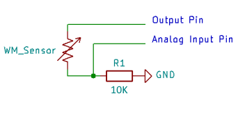
To measure resistance inside the sensor, typically a voltage divider circuit is used. The circuit uses a known input voltage, output voltage, and series resistor value to calculate the value of another resistor (the sensor). Figure 1 is a simple example using a digital pin for power and an analog input to read and measure the resistance of the sensor.
Once the resistance is known, the value is calibrated to soil water tension via a series of equations or referencing look-up tables. The WATERMARK sensor can be read by devices such as Arduino/ Raspberry Pi etc., provided some guidelines are maintained with the reading circuitry and program.
For adapters which will read the sensor and output the values in a more standard format such as an analog 0-3V or SDI-12, click here.
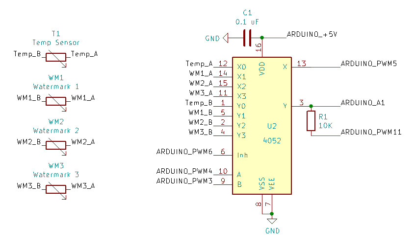
R=10000*(Vs-A1)/A1